Instructions for manual mapping
Storyboard 
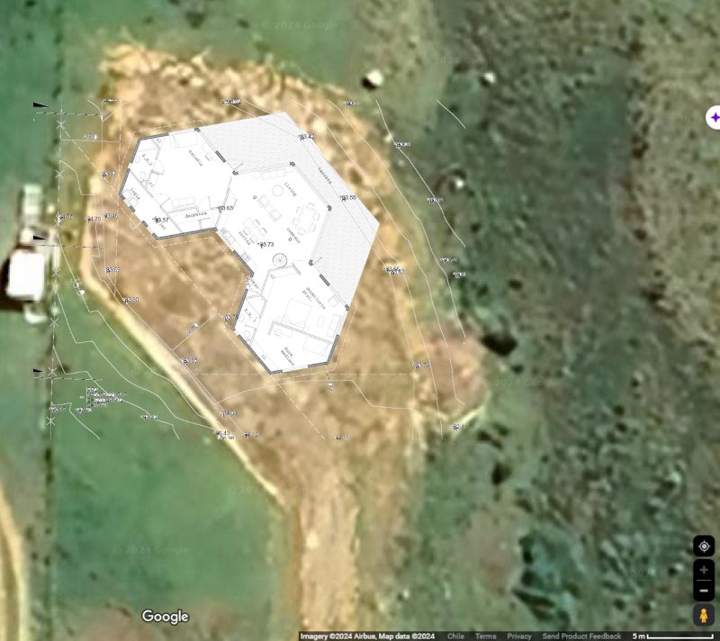
Given the shape of the house (hexagonal), geometric relationships can be utilized to directly map the house's floor plan onto the ground.
ID:(110, 0)
Materials
Description 
The following steps describe how to manually transfer the blueprint to the terrain as defined.
To do this, you will need:
• 23 pointed iron stakes for marking (e.g., 20 cm long and thin). Optionally, you can attach labels with point designations to avoid confusion.
• A hammer for driving the iron stakes.
• A tape measure or equivalent measuring equipment capable of measuring up to 10 meters.
• String to mark the 20-meter baseline.
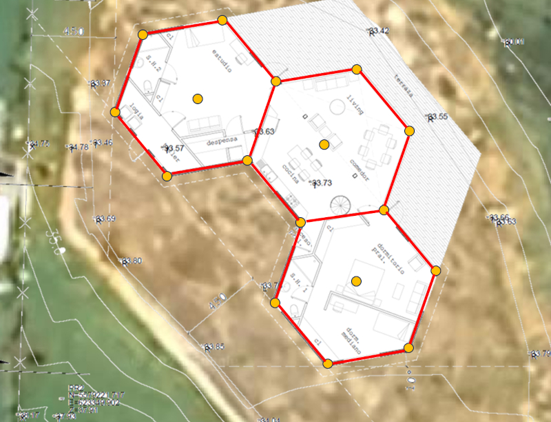
• Once the key points are secured, you can use lime with a small pickaxe to mark the lines on the terrain.
ID:(718, 0)
Baseline drawing
Description 
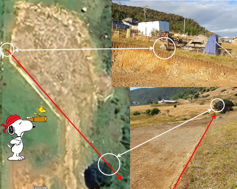
To draw the baseline, you can locate the rock on the uphill side of the embankment, facing west. From there, you can look towards the myrtle tree on the southeast side near the road and consider an imaginary line on the embankment between the rock and the tree:
To begin defining the line, a person needs to go to the corner near the rock but on the embankment and extend a rope or cord in that direction for 20 meters. The person on the rock should ensure that the rope is taut and, therefore, straight. For this purpose, you can secure the first iron stake at point "O" at the corner on the flat area of the embankment:
Once the rope has been extended, it needs to be measured along it first for 2 meters and then three times for 4.5 meters each. Each time you measure, you should drive iron stakes into the ground and ideally mark them with the letters "O," "A," "B," "C," and "D."
ID:(719, 0)
Construction of the first point
Description 
The method for constructing and achieving high-quality angles involves using the compass technique. In this technique, the goal is to draw arcs with defined radii from two points and find the point where they intersect.
The first point to be drawn using this method is the center of the backyard. To do this, a cord is required with two fixed loops (they should not slide) separated at a distance of 6.36 meters.
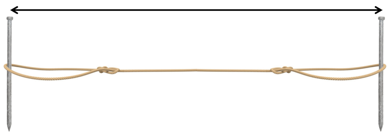
The measurement at the first point is 6.36 meters (it's crucial that any discrepancy is within a few millimeters, not centimeters. These initial arcs are the only ones performed with a distance of 6.36 meters.
Each time, one of the already hammered iron stakes is used, and with it, the corresponding arc is marked on the ground. Then, move on to the second iron stake and repeat the exercise to create a second arc. Finally, drive the iron stake into the point where both arcs intersect.
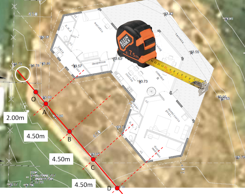
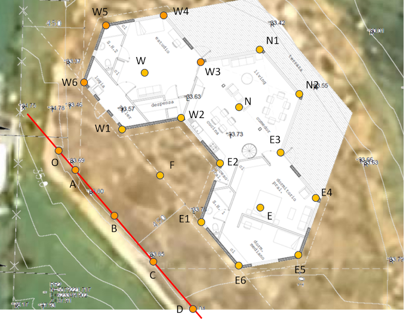
In this case, the first arc is drawn with the center at point "A," and then the second arc is drawn with the center at point "C." Identifying these points helps avoid confusion and allows for a more straightforward procedure. The new point resulting from the intersection is located at the center of the backyard and is named "F." Once the iron stake "F" has been driven in, you can verify the correctness of the diagram. To do this, you can measure the distance between points "F" and "B" with a tape measure, which should result in 4.5 meters.
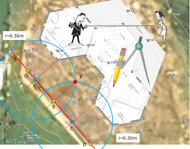
If the result does not match, it is necessary to identify the error and make corrections to obtain the correct position for "F."
ID:(720, 0)
Construction of the two initial points of the perimeter
Description 
Once the point "F" has been located, we can obtain the initial points for the perimeter of the house.
Firstly, we will determine the right corner of the western module. To do this, we will use a slightly shorter cord than the one used previously. Therefore, we need to prepare a new cord with a distance of 4.5 meters between the iron stakes. This cord will be used for all subsequent measurements.

The measurements at the following points are 4.5 meters (it's crucial that any discrepancy is within a few millimeters, not centimeters). All subsequent arcs are measured with a radius of 4.5 meters.
The point where the two arcs with centers at "A" and "F" intersect is denoted as "W1."
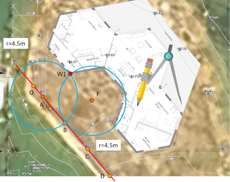
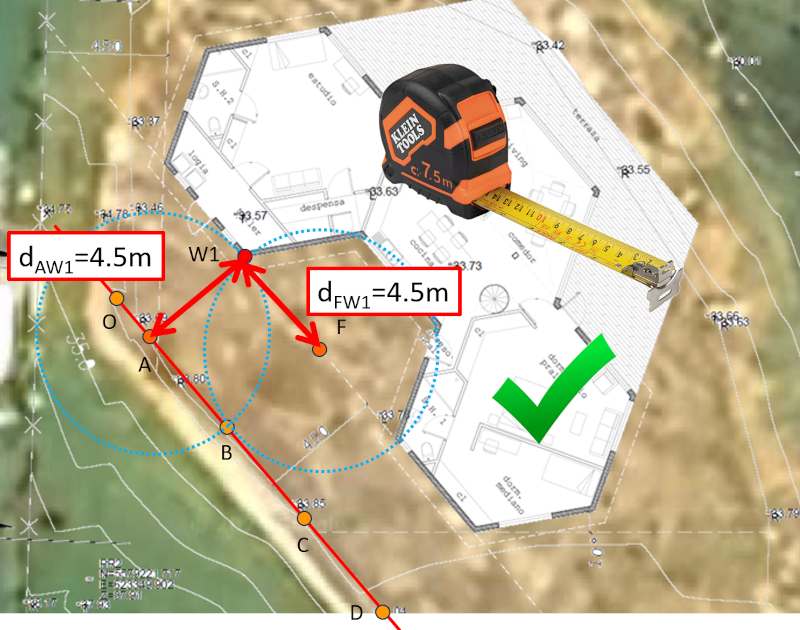
As in the previous step, we can verify whether the operation was carried out correctly. To do this, we need to measure the distances from "A" to "W1" and from "F" to "W1," and in both cases, the measurement should be 4.5 meters.
Once we have obtained the point "W1," we can determine the equivalent on the eastern side of the module. To do this, we draw arcs using the centers "C" and again "F."
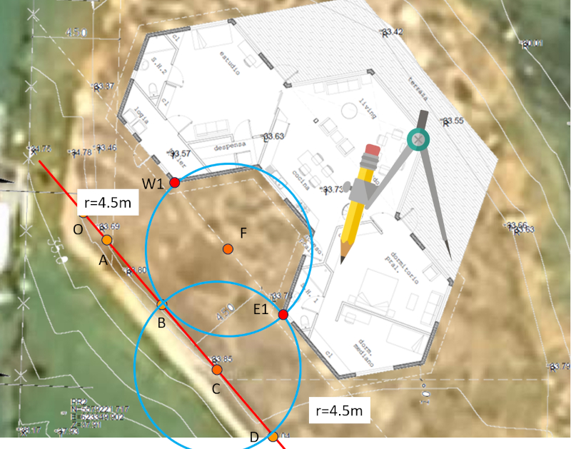
We will call this new point "E1," and once again, it is important to check if it has been determined correctly. To do this, we measure the distances from "C" to "E1" and from "F" to "E1." Both distances should measure 4.5 meters.
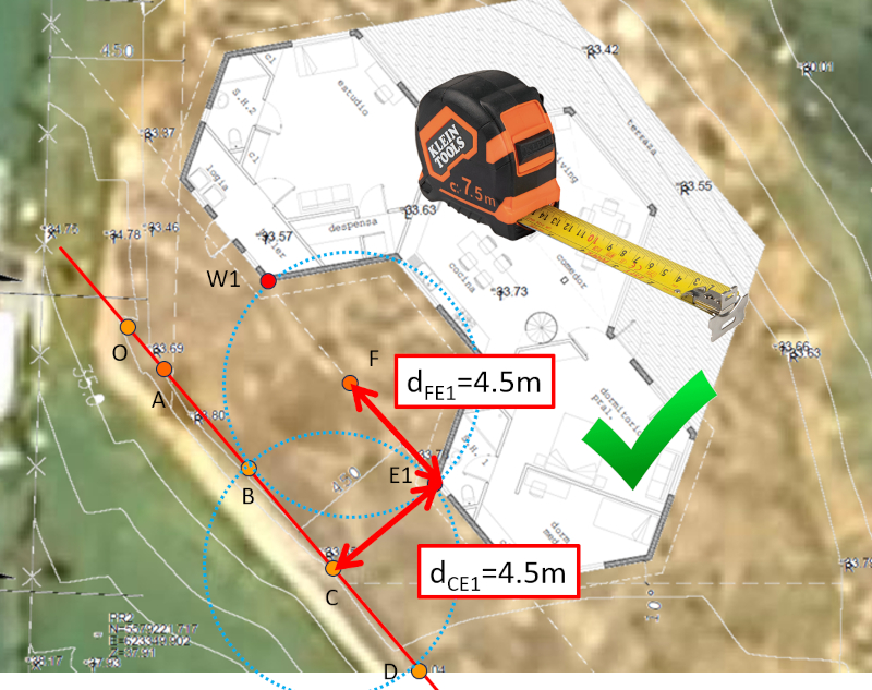
ID:(721, 0)
Construction of the centers
Description 
In order to construct the centers of each module, it is first necessary to obtain two points on the perimeters. This is achieved using the newly found points and the central point of the courtyard.
Using points "F" and "W1" as centers, we obtain point "W2" at the intersection of the arcs, which is located near the central module on the left side:
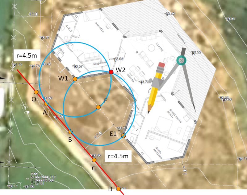
Similarly, point "E2" on the right side is obtained by drawing arcs with centers "F" and "E1":
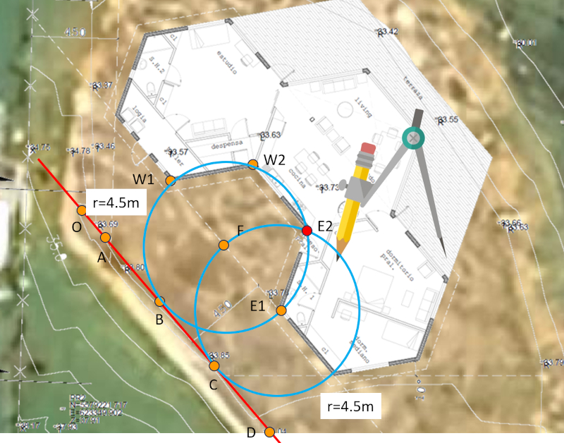
Once we have points "W1," "W2," "E2," and "E1," we can construct the arcs that define the centers of each module.
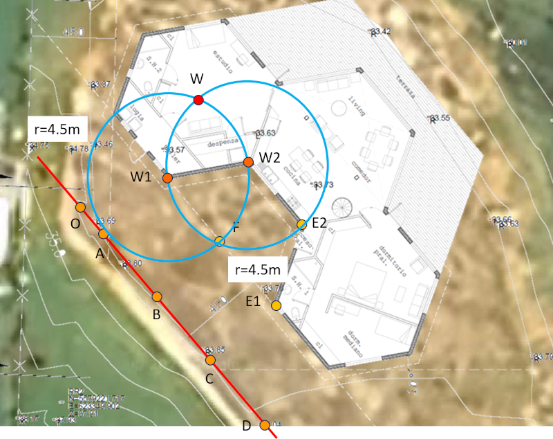
Firstly, the module to the west. Using points "W1" and "W2," we create two arcs that intersect at the center of the module, which we will call "W":
Next, we determine the center of the central module. Using points "W2" and "E2," we create two arcs that intersect at the center of the module, which we will call "N":
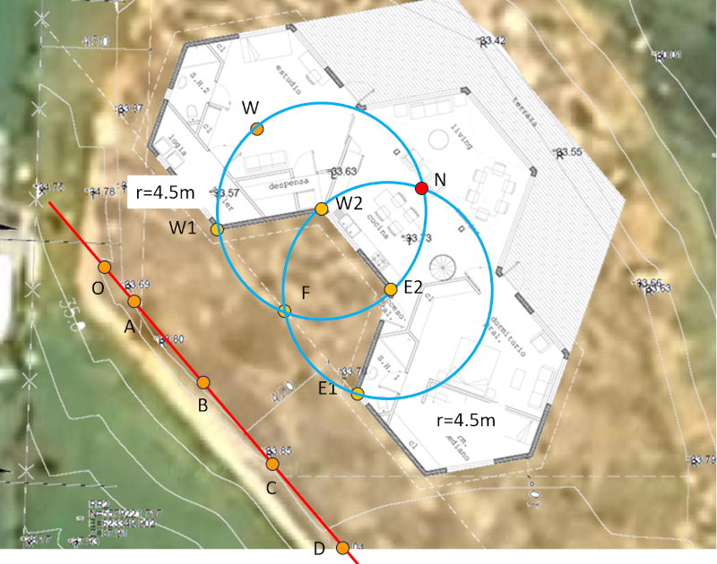
Finally, the module to the east. Using points "E2" and "E1," we create two arcs that intersect at the center of the module, which we will call "E":
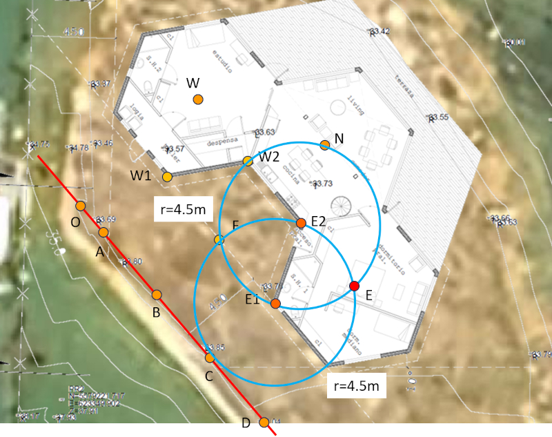
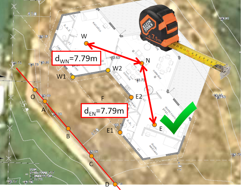
To verify that we have worked correctly, a simple check can be performed by measuring the distances between points "W" and "N" and between "E" and "N." Both distances should be 9.0 meters:
With the centers determined, we can easily complete the perimeters.
ID:(722, 0)
Perimeter construction
Description 
To complete the perimeters, an arc is drawn from the centers in each case (first "W," then "E," and finally "N"). Since it is a process that covers the entire perimeter, it is helpful to draw full circles around the three centers, which saves time by not having to draw a segment each time.
For the western module (W), the following points are determined as follows:
Using centers "W" and "W1," point "W6" is determined at the intersection of the arcs:
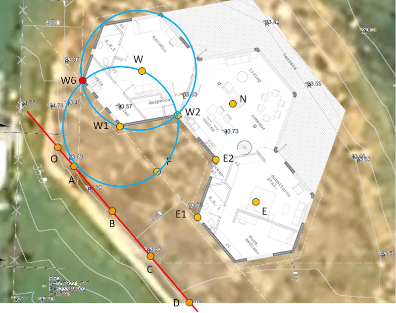
Using centers "W" and "W6," point "W5" is determined at the intersection of the arcs:
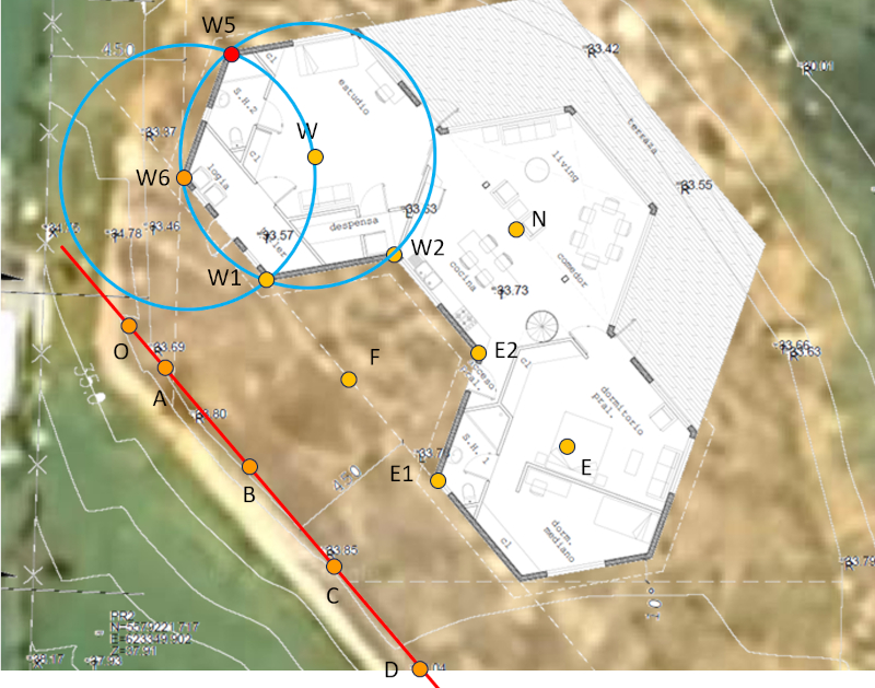
Using centers "W" and "W5," point "W4" is determined at the intersection of the arcs:
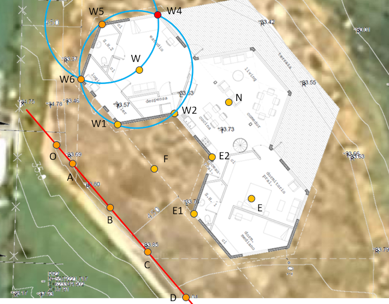
Using centers "W" and "W4," point "W3" is determined at the intersection of the arcs:
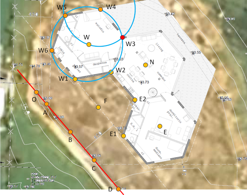
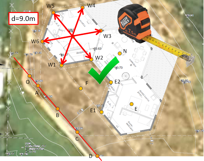
Finally, the correct execution can be verified by measuring the three diameters, which should each be 9 meters:
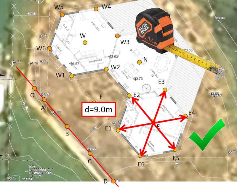
For the eastern module (E), the following points are determined as follows:
Using centers "E" and "E1," point "E6" is determined at the intersection of the arcs:
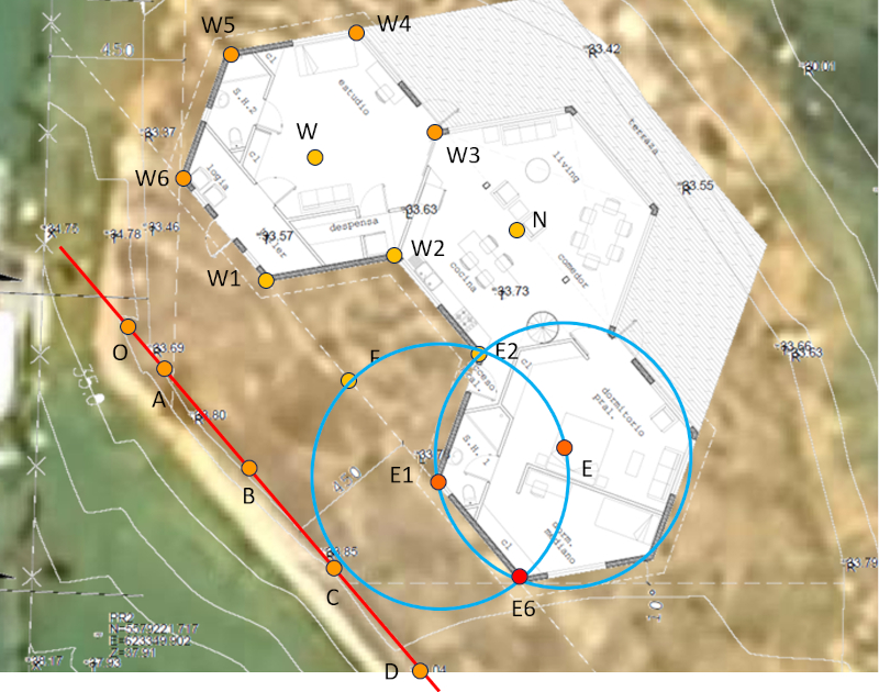
Using centers "E" and "E6," point "E5" is determined at the intersection of the arcs:
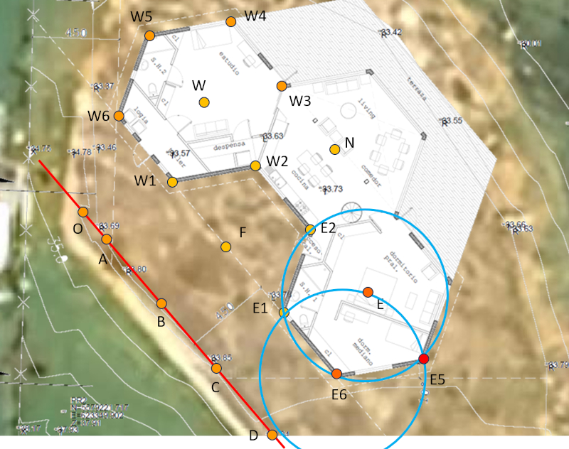
Using centers "E" and "E5," point "E4" is determined at the intersection of the arcs:
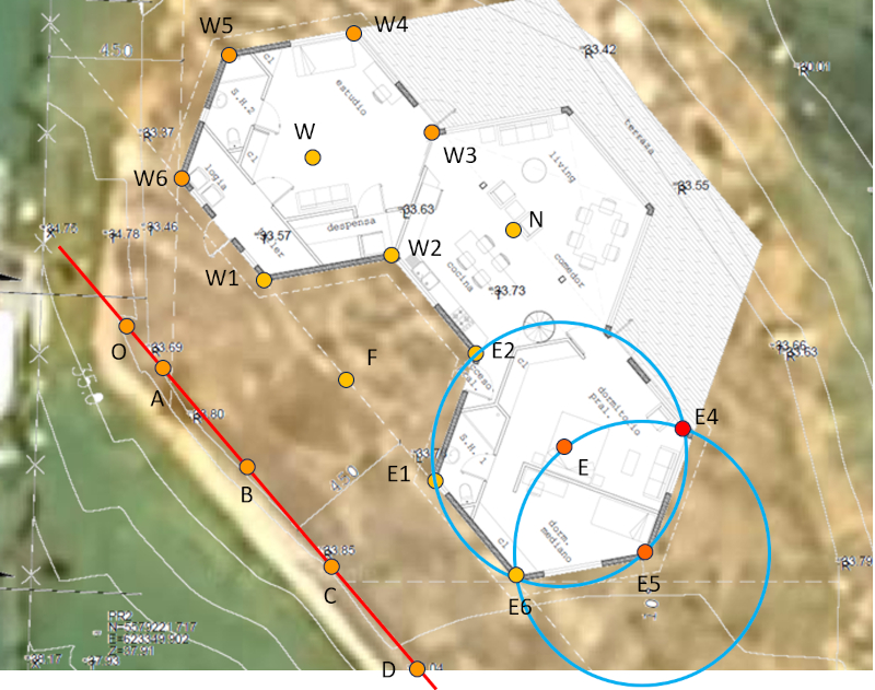
Using centers "E" and "E4," point "E3" is determined at the intersection of the arcs:
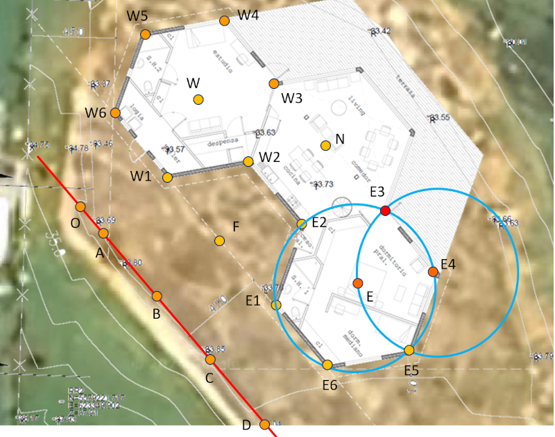
Finally, the correct execution can be verified by measuring the three diameters, which should each be 9 meters:
For the central module (N), the following points are determined as follows:
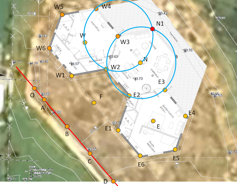
Using centers "W3" and "N," point "N1" is determined at the intersection of the arcs:
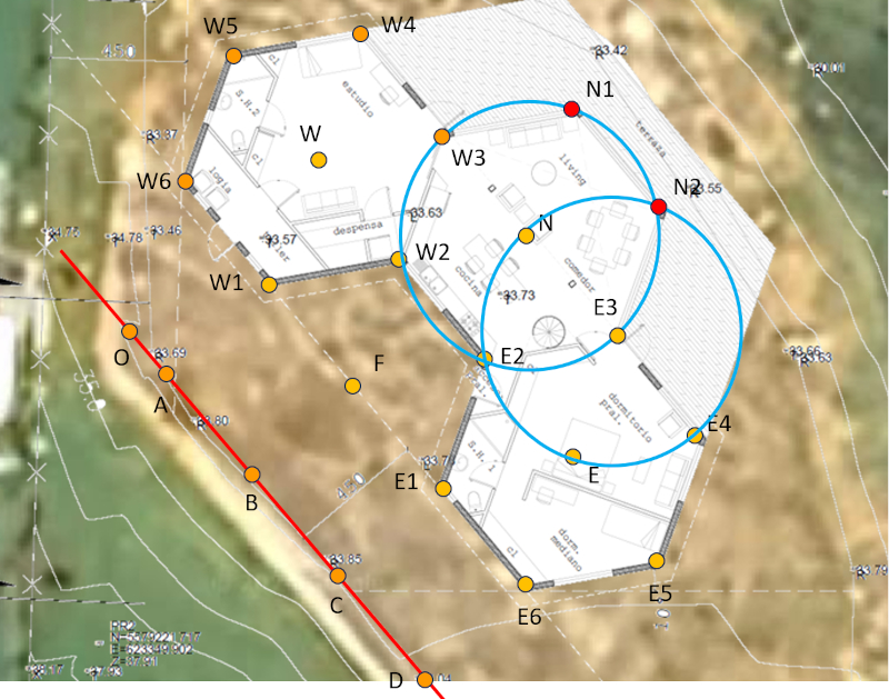
Using centers "E3" and "N," point "N2" is determined at the intersection of the arcs:
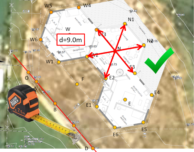
Again, the correct execution can be verified by measuring the three diameters, which should each be 9 meters:
ID:(723, 0)
Perimeter closure
Description 
Once all the points are marked, you obtain a diagram like this:
This makes it easy to mark the edges with lime:
ID:(724, 0)
