Modeling method
Storyboard 
In order to conduct various analyses, it is essential to have a simplified model of the house. To achieve this, an initial coordinate system is established, serving as a reference for defining all the key points. Using these points, it is possible to establish planes for the walls, ceilings, and floors. Additionally, doors and windows can be incorporated into the walls as needed.
ID:(92, 0)
Basic model
Description 
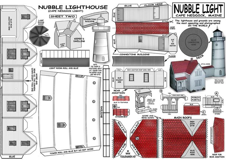
The basic model consists of a series of points that correspond to the corners of surfaces. This modeling approach is similar to how in the past, models of houses, boats, and planes were assembled by cutting sheets of cardboard and assembling them:
In our case, we identify points at the corners of walls, ceilings, and floors. Groups of these points come together to form these surfaces, as in this example showing the front wall of the lighthouse house:
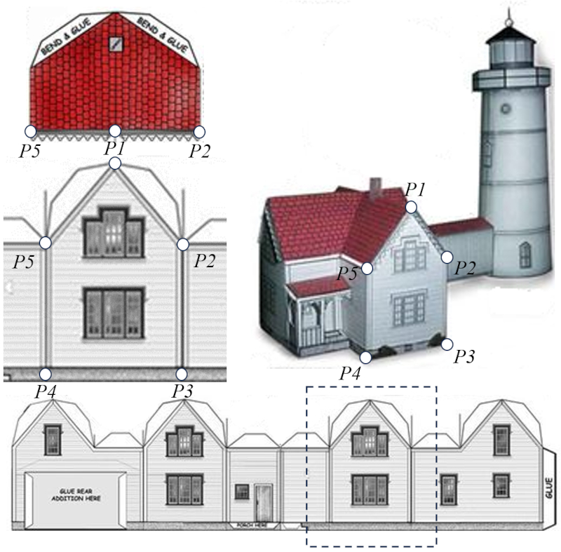
The points on the facade are also points on the side walls, the ceilings, and the floor, although this is not visible in this diagram.
ID:(438, 0)
Coordinates
Description 
To begin, it's essential to define a coordinate system through which all points and subsequently surfaces will be defined. Since the coordinate system can be rotated later, and thus the entire design, it's not crucial to fix an orientation based on how the house will be oriented. Instead, the goal is to establish a system that is convenient for defining the structure.
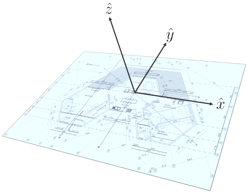
In the case of this project, we used a point on the ground as the origin, located at the center of the module that houses the living room, dining area, and kitchen. The orientation was set up so that the z-axis runs along the vertical lines, the y-axis lies between the center of the hexagon and the midpoint of the main window's edge (i.e., along the line that separates the living room from the dining area), and finally, the x-axis is positioned orthogonally along the line that runs from the front of the study to that of the bedroom.
ID:(588, 0)
Points
Image 
Once the coordinate system has been defined, we can proceed to define all the points that represent the various surfaces. To do this, we need to specify distances along the $\hat{x}$, $\hat{y}$, and $\hat{z}$ axes from the origin associated with the system.
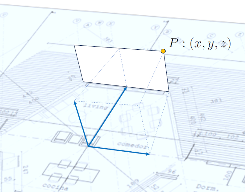
Furthermore, to facilitate surface definitions, it is convenient to establish some code or name for each point. This can include logic, such as indicating the level of the points with an initial number or letter, followed by a separator like a period, and a consecutive number. For example, '0' for the ground level, '1' for the ceiling level, so the fifth point on the first level would be denoted as $P_{0.5}$.
ID:(589, 0)
Vectors
Equation 
With two points, you can define a vector by subtracting the coordinates of one point from the coordinates of the other.
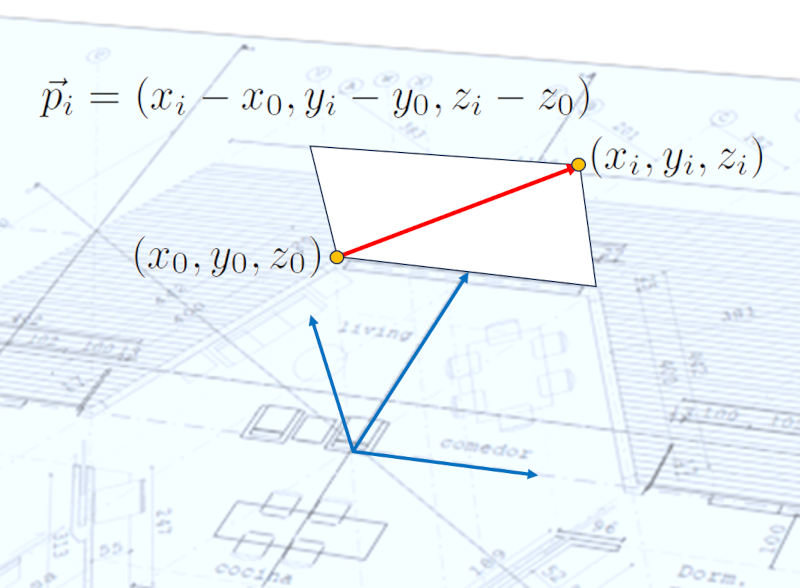
This concept is expressed through the calculated components of each difference and is denoted by a letter with an arrow above it:
ID:(595, 0)
Vector length
Equation 
With two points, you can define a vector by subtracting the coordinates of one point from the coordinates of the other. Therefore, each component of the vector corresponds to a side of a prism. If you observe the points in a plane, the geometric figure reduces to a triangle:
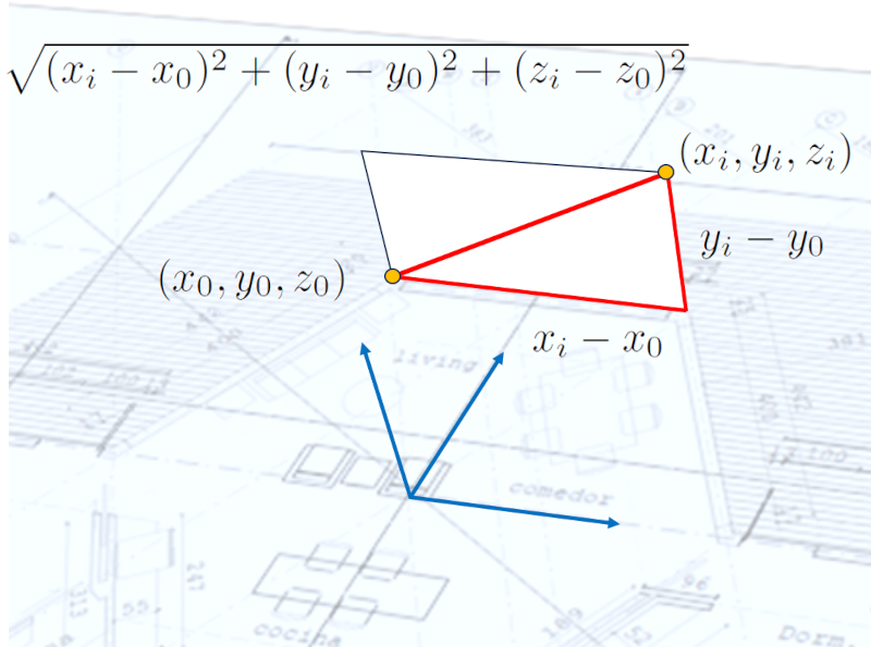
In general, the length of the vector can be calculated using the Pythagorean theorem, and the result is the magnitude of the vector:
This is referred to as the magnitude of the vector.
ID:(596, 0)
Surfaces
Description 
Every surface consists of at least three points, which corresponds to a triangle. A rectangle consists of four points, while a more complex shape like a hexagon uses six points.
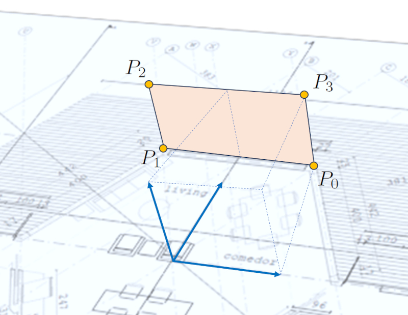
To define a surface, you must specify the points that make it up in the order they should be connected. Additionally, you can assign a name to each surface to facilitate later identification.
To avoid problems, it's important to keep in mind that:
It's crucial to remember that all the other unit vectors that can be defined with the remaining points and the same origin must lie in the same plane as defined by the first and last vectors. Otherwise, the surface won't be flat.
ID:(590, 0)
Versor
Equation 
To calculate light and solar heating fluxes, it's necessary to work with the normal direction to surfaces such as windows, walls, and ceilings. To obtain this direction, we need to normalize the corresponding vector, which means dividing it by its length so that its length is always one unit, regardless of the direction it points.
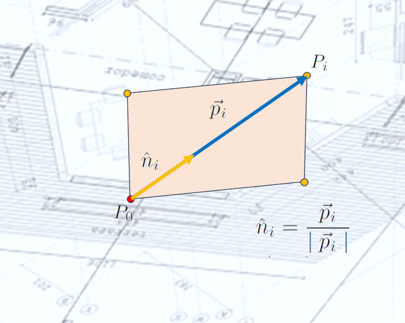
Therefore, the unit vector (denoted with a hat instead of an arrow, for example, $\hat{x}$) is defined as the vector to the $i$-th point $\vec{p}_i$ divided by its magnitude $\mid\vec{p}_i\mid$:
ID:(597, 0)
Surface area
Equation 
The area of the parallelepiped generated by two vectors can be directly calculated from the magnitude of their cross product. Therefore, if you want to calculate the area between successive sets of vectors, you can do so as follows: the first area is calculated between vector $\vec{p}_2$ and vector $\vec{p}_1$, the second between vector $\vec{p}_3$ and vector $\vec{p}_2$, and so on. This can be visualized better with an example of four points:
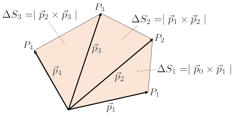
In general, the total area is calculated as follows:
ID:(594, 0)
Versor normal to the Surface
Equation 
If we take the first point $P_0$ of the sequence of points defining a surface as the origin, the second point $P_1$ to define the first unit vector $\hat{n}_1$, and the last point $P_N$ to define the second unit vector $\hat{n}_N$, we can define the normal unit vector to the surface as follows:
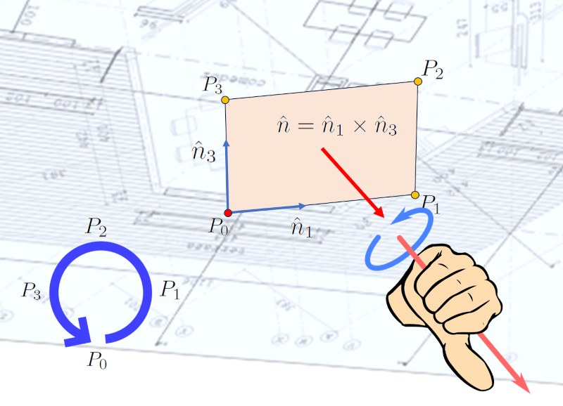
Since unit vectors are, by definition, normalized, the cross product is also normalized, meaning that the result reflects a direction.
To perform the calculation, we can work with the unit vectors $(n_{1,x}, n_{1,y}, n_{1,z})$ and $(n_{N,x}, n_{N,y}, n_{N,z})$. We can use the following equation:
$\hat{n}_1\times\hat{n}_N=(n_{1,y}n_{N,z}-n_{1,z}n_{N,y},n_{1,z}n_{N,x}-n_{1,x}n_{N,z},n_{1,x}n_{N,y}-n_{1,y}n_{N,x})$
ID:(591, 0)
Windows and doors
Image 
For the definition of doors and windows, we work with a local coordinate system defined by the unit vectors that were used to calculate the normal unit vector, which are $\hat{n}_1$ and $\hat{n}_N$. We work on the surface where the unit normal vector is positive. We start by defining the bottom-left corner of the door or window. Then we specify the width and height of it.
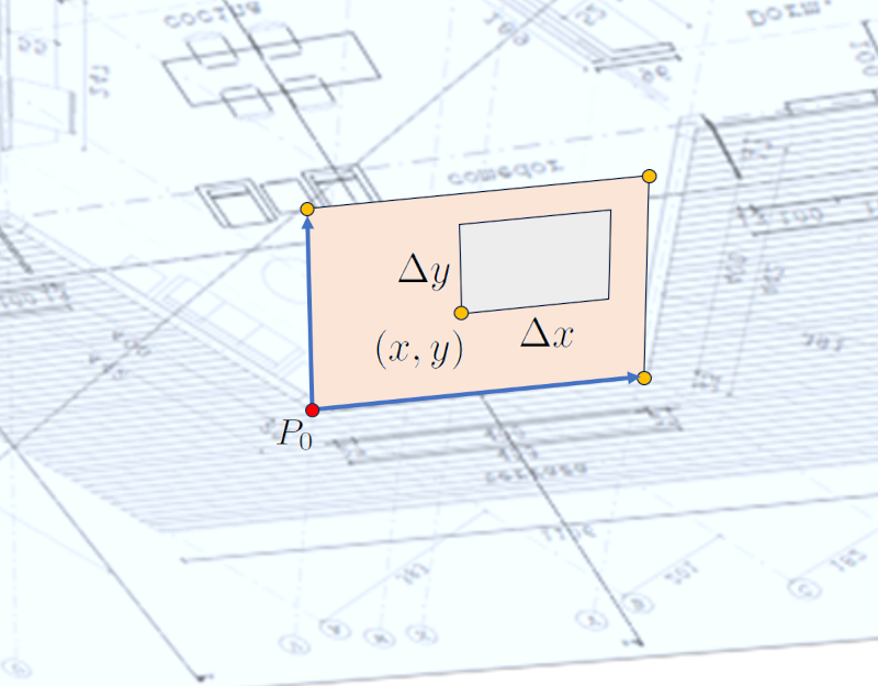
Each window and door is defined individually.
ID:(592, 0)
House rotation
Image 
Once the points, surfaces (walls, floors, and ceilings), windows, and doors have been defined, it's possible to rotate the design. This is because in the initial definition, it's convenient to use the simplest possible coordinate system, which may not necessarily align with north as the $\hat{y}$ axis and east as the $\hat{x}$ axis. However, rotation, typically around the vertical $\hat{z}$ axis, allows for the expression of the entire design in a coordinate system that is spatially more convenient:
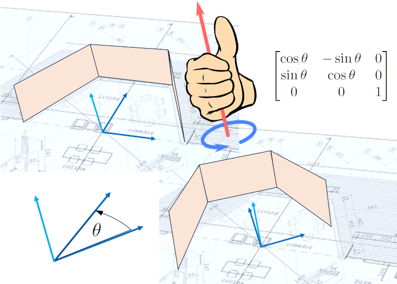
Rotation shifts all the points and, consequently, all the vectors and unit vectors that have been calculated. This is important because it allows for the study of how light interacts with the structure.
ID:(593, 0)
